Датчик почвы датчик азота фосфора и калия быстрый измерительный прибор
3124.8


Сохраните в закладки:


*История изменения цены! Указанная стоимость возможно, уже изменилось. Проверить текущую цену - >
| Месяц | Минимальная цена | Макс. стоимость | Цена |
|---|---|---|---|
| Aug-15-2025 | 113.4 руб. | 115.53 руб. | 114 руб. |
| Jul-15-2025 | 92.42 руб. | 94.16 руб. | 93 руб. |
| Jun-15-2025 | 111.31 руб. | 113.23 руб. | 112 руб. |
| May-15-2025 | 110.73 руб. | 112.13 руб. | 111 руб. |
| Apr-15-2025 | 88.96 руб. | 90.11 руб. | 89 руб. |
| Mar-15-2025 | 109.70 руб. | 111.80 руб. | 110 руб. |
| Feb-15-2025 | 108.69 руб. | 110.49 руб. | 109 руб. |
| Jan-15-2025 | 107.75 руб. | 109.27 руб. | 108 руб. |
Новые товары
Характеристики
Описание товара
This bridge ismeasureReflectance coefficient sensor for radio frequencynetworkMeasurement,The output reflected signal has both amplitude and phase information.It has the characteristics of wide frequency and high directivity. The simple application of this bridge can be combined.beltTracking Source Radio Frequency Spectrum Analyser or Sweeper,It can measure the echo loss of the device and the reflection of the whole frequency band. For example, the vector impedance of the circuit can be accurately measured by combining the vector voltmeter or the vector voltage measuring device with the signal source, and the test and debugging of the RF matching circuit can be completed. Widely used in antenna measurement and debugging, radio frequency circuit andRadio and TVandCommunication equipmentetc.Measurement and debugging.
Model: AYT-1
Frequency range: 1MHz~1GHz
Characteristic impedance: 50 & Omega;
Direction: & ge;35dB
Maximum input power≤ 0.2W
Insertion loss: 6.5dB & plusmn; 0.5dB (from & ldquo; input & rdquo; end to & ldquo; Measurement & rdquo; end)
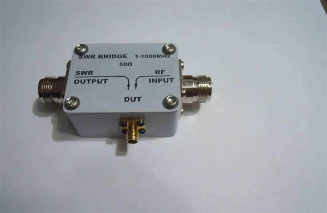
Connector Form: & ldquo; Input & rdquo; End,Output & rdquo;,"Measurement & rdquo;All areN Female
Size:95×65×32(L× W× H) mm
For bridge orientation, we generally take 35dB as the eligible standard and 30dB as the fault standard.PRACTICAL RADIO FREQUENCY TECHNOLOGY P135
The bridge.Direction is the whole section of the capital-ge;35DB, middle and low frequency & ge;40dB
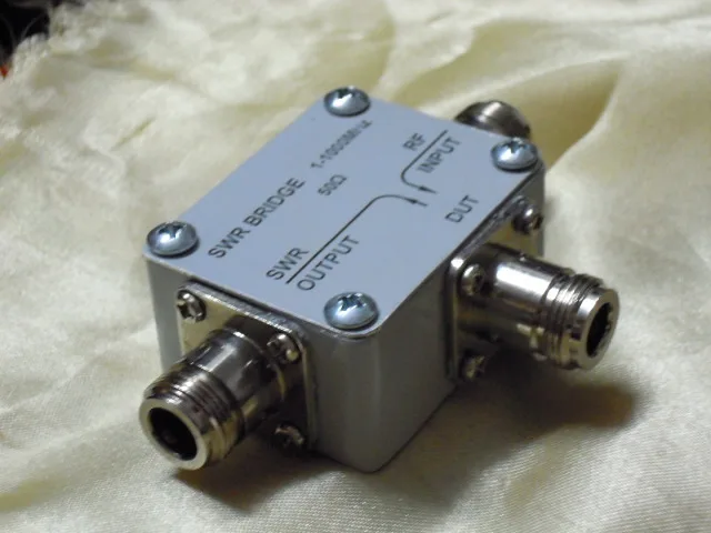
If you need a SMA bridge as shown in Figure 2, please contact the shopkeeper. No connection, default send three N-head bridge.
Following is an introduction to the general use of reflective bridges:
1. Reflective Bridge Orientation Self-calibration
1.1 The output of the tracking signal source of the reflector bridge spectrograph is set at the frequency range of 1-1000MHz, 100 MHz per cell horizontally, and the output amplitude of the tracking signal source is 0 dBm (other can be done, the following are measured according to the output of 0 dBm).
1.2 Reflector bridge DUT (device under test) open circuit. (No connection, low frequency, low requirements can be done; high frequency, high requirements, open circuit, because there are test terminals (position benchmarks), inner core open circuit capacitance of external conductors... And so on, can not be N simple open circuit), 1GHz signal is not high, we can simply N open circuit. Record the amplitude of the spectrometer. As shown in Figure - 14dBm

1.3 Reflective Bridge Self-calibration
DUT is connected with 50 Euro precision load to see how much the amplitude of the spectrum meter decreases. The bigger the better. Under 1GHz, 35 dB is qualified and 40 dB is excellent. 30dB is a fault. When the frequency is several GHz, about 30 dB can also be used. When the frequency is several GHz, it is not easy to reach 30 dB. It can be understood that if the 50-Euro precision load and the corresponding 50-Euro (etc.) perfectly ideal condition in the reflective bridge, then the reflective bridge is completely balanced, and there is no output, that is, the amplitude drop is infinite, of course, this is impossible. As the spectrum analyzer is connected with two kinds of precise loads, the two amplitudes are less than - 50 dBm, and the decrease is more than 36 dB, (- 14 - (- 50) = 36), that is to say, the directivity of the reflective bridge is better than 36 dB. The result of directional self-calibration is qualified

Self-calibration results of another 50 Euros precision load 
If there is no 50 Euro precision load or the load accuracy is not enough, the self-calibration step can be completely omitted.
2. Measure the return loss of the measured piece.Reflectance coefficient and standing wave ratio can be calculated mutually, one can be calculated for the other two) If the backlash is 20 dB, thenThe reflection coefficient is 0.1 and the standing wave ratio is 1.22.Formulas, software and charts can be used to calculate each other more conveniently.
2.1 Measure the actual antenna parameters, as shown in the figure, the measured antenna is a small antenna of 432 MHz.
1-1000MHz Full Section View

20MHz measurement per cell

It can be seen that at the central frequency, the antenna return loss is about 20 dB (about two cells, 10 dB per cell vertically).That is to say, the reflection coefficient is 0.1, the standing wave ratio is 1.22, and the antenna return loss is 10 dB.Reflection coefficient 0.32, standing wave ratio 1.92)The bandwidth is about 20MHz (two half cells), that is, 10% of the power is used.The bandwidth of reflection is 20MHz.
2.2 Measuring a Device
If the blue label device is attached to the figure, the amplitude is about - 34 dBm, i.e. the return loss is about 20 dB.

What device? As can be seen from the figure, the attenuator is 10dB (frequency up to 12.4 GHz).

The return loss is 20 dB, twice as much as 10 dB. It's a coincidence to understand that the signal passes through the 10 dB attenuator at the DUT end of the bridge to the open circuit (nothing is connected at the other end of the attenuator). What is the open circuit? The open circuit is S11. The open circuit is full reflection. The reflected signal at the open end passes through the 10 dB attenuator and returns to the DUT end of the bridge, which attenuates 20 dB altogether. This is not really the “ meaning ”.
2.3 The return loss of the blue 10dB attenuator is 20dB when it opens the circuit. You know, what else can you do? The return loss is 20dB.Corresponding reflection coefficient 0.1, reflection coefficient
Γ=(Z-Zo)/(Z+Zo)0.1=(Z-50)/(Z+50), ZSolve 61.1 ohms. Look at the picture. Measure the attenuator resistance with a multimeter. 61.9 ohms. Compare.The error is less than one euro. The original spectrum analyzer (with tracking signal source or external signal source, or high-frequency millivolt meter plus signal source) plus reflection bridge can also measure & ldquo; impedance & rdquo; (scalar impedance). (The actual measured impedance is the impedance on the Smith circle with a reflection coefficient of 0.1. The attenuator can work to 12 GHz. The reactance effect is neglected without considering the reactance effect. One of the two points where the impedance of 0.1 circle intersects with the real axis is 61.1 ohms). If there is a vector voltmeter, the vector impedance can be measured completely, that is, the network analyzer can measure S11.


Часы просто идеальные. Купила их на подарок своему парню. Они в таком вот олдскульном стиле, если можно так выразиться. Смотяртся... Читать отзыв полностью...

Абсолютно не ясно, как подключить. Может кто прояснить ?... Читать отзыв полностью...

Сделала покупку у данного продавца впервые. Купила на свой страх и риск два комплекта сразу: для мальчика и девочки. Ткань-... Читать отзыв полностью...


Давно хотела себе именно такие часы. В золотом корпусе с украшениями. Если сказать буквально в нескольких словах, то они просто... Читать отзыв полностью...

Очень нужная вещь в каждом доме. заказала себе 3 штуки, так как у нас очень много лекарств дома и они... Читать отзыв полностью...


Какая цена этого товара?Могу ли я купить и получить этот товар с доставкой в РФ г ВОЛГОГРАД.Оплата б/к" МИР".... Читать отзыв полностью...